
Like the takeoff and landing phases for aircraft, the startup and shutdown phases for a power supply can be critical. Control logic must be in the correct state before power is applied to high-power switching components.
We had this driven home on a recent project. Energizing the power would sometimes destroy a MOSFET switching bridge. A growing pile of dead components motivated some careful scrutiny of the design. Eventually we realized that the logic power had to be up and stable some milliseconds before applying main power. We designed a delay and comparator circuit that generated the correct sequence, and now we needed to test it.
Capturing this type of one-shot event is used to be expensive and difficult.
One possibility was a scope camera. (The image shows a Tektronix C-30 camera on a Tek 454 scope.) You set up the oscilloscope trigger for single shot, loaded the camera with film, opened the shutter, and then energized the circuit. With luck, you caught the waveforms on film. More likely, you had to tinker with the trigger level and beam intensity to get something useful.

Another possibility was the analog storage oscilloscope. Tektronix had a bistable storage display, Hewlett-Packard had a variable persistence display. They worked, but were *very* expensive. They didn’t create a permanent record.
Furthermore, neither the camera technique or the analog storage technique could show you much time before the trigger event.
Fast forward to the present: the CGR-101 is ideal for this type of measurement. It’s a digital storage scope, so it can capture and display a single event. The trigger level can be set precisely by adjustment of a cursor with readout of the trigger voltage. And the trigger point can be adjusted to show events before, during or after the trigger event. And the resulting display can be saved or printed.
The figure shows schematic of the supply sequencer.

The output of the 78L05 regulator pops up to 5 volts immediately after input power is energized. The 5k1 and 49k resistors establish a voltage of about 4.4 volts on one input of the comparator. The 1M resistor then charges the 100n capacitor with a time-constant of 100 milliseconds. When the capacitor voltage reaches 4.4 volts, the output of the comparator goes low, turning on the IRF9510 power MOSFET. This applies the main power to the rest of the circuit.
Here are the measurements for this circuit. The first figure shows the turn-on sequence.
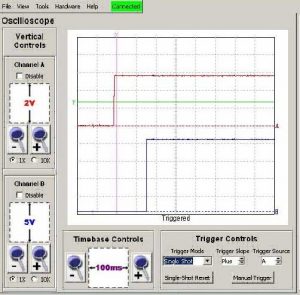
The upper trace is the 5 volt logic signal. The lower trace is the 20 volt main power. We need to ensure that the logic is powered up some tens of milliseconds before the main power is applied. The scope trigger level is indicated by a horizontal green cursor with T at the left. This has been set to trigger from the rising (plus) slope of the logic signal, when the logic reaches roughly 3 volts. The vertical ‘trigger point’ cursor, marked by an X at the top, sets the position of the trigger point on the screen – in this case, about 200 milliseconds from the left edge of the display. It’s clear from the captured traces that the logic supply comes up 150 milliseconds before the main power.
Now the turn-off sequence, shown in the second figure. In this case, things are reversed: we need to remove the main power before the logic power. In this case, we set the the trigger level is set a bit higher we trigger off a negative going (minus) slope. As shown in the captured traces, the main
power dies away to zero while the logic supply is still above 3 volts. The HC logic in this system will function correctly with a power supply voltage of 2 volts or greater so the logic is still working correctly when the main power is removed and the unit should shut down gracefully.

We have a number of sophisticated and expensive oscilloscopes available to us in our lab. The CGR-101 is the only one that could capture this type of information.
Leave a Reply
You must be logged in to post a comment.