Introduction to Electronics Kit
Overview
We created the Introduction to Electronics Kit as a fun, hands-on way to build some basic electronic circuits and gain some exposure to electronic test equipment.
In these lab exercises you will build some electronic circuits and use instruments to measure the behavior of these circuits. You will also learn some concepts and vocabulary about electronics. These lab notes are geared towards Syscomp instruments, but they can be adapted to any lab environment.
Equipment
You will need the following equipment and materials for these lessons:
- Introduction to Electronics parts kit. (A list of compnents can be found here)
- Syscomp CircuitGear Instrument
- Multimeter with DC voltage, DC current (mA) and resistance measurement capability
Install the Software
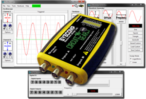
The Syscomp CircuitGear series of instruments are ideal because they include all the instruments necessary to measure the behavior of our lab circuits. The CircuitGear MKII, Circuit Gear Mini, and Signature Analyzer instruments are all suitable for these exercises and all use the same unified software.
The software can be downloaded here.
Electronic Diagrams
Wiring Diagram
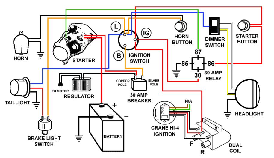
A wiring diagram shows an image of the physical circuit wiring. From an electronics standpoint, it includes some irrelevant details such as the shape and placement of the components.
Schematic Diagram

A schematic diagram represents the elements of a system using abstract, graphic symbols rather than realistic pictures.
For example, a subway map (subway schematic) may represent a subway station with a dot. The dot doesn’t resemble the actual station at all but gives the viewer information without unnecessary visual clutter.
A circuit schematic omits alls details that are not relevant to the function of a circuit.
Schematic Symbols

The image above shows a collection of different electronic schematic symbols that would commonly be found on a schematic.
Our Schematic Symbols
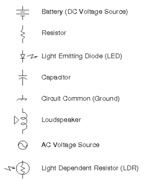
For these lab exercises we will be using this subset of schematic symbols.
Take a minute and see if you can match the symbols above to the components in your parts kit.
Assembling the Circuit
A solderless breadboard is an easy way to prototype simple electronic circuits.

A Solderless Breadboard
The breadboard allows us to connect electronic components together without soldering by plugging them into holes in the board.
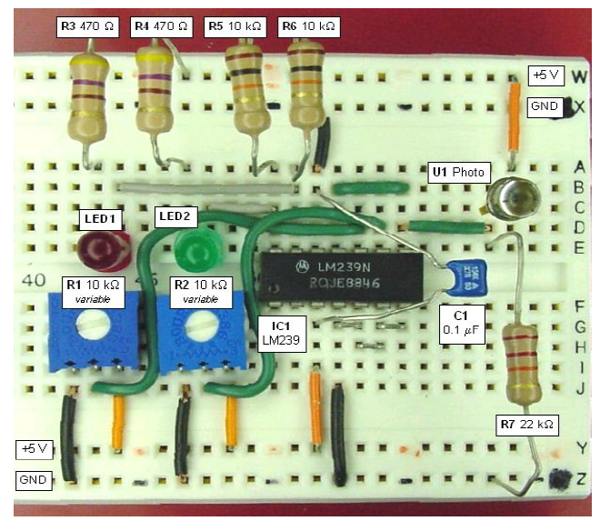
Example of a Circuit on a Breadboard
Breadboards are arranged in rows and columns of connected holes. Electronic components can be connected together by plugging them into the board. The image below depicts how the holes are connected on the board.

The red lines indicate which holes are electrically connected together. The long horizontal rows on the top and bottom are usually used to route power through the board. The shorter vertical lines are used to connect component pins together.
Sparkfun Electronic has a great article on How to Use a Breadboard.
Resistor Color Codes

The resistance of a resistor is represented by colored bands printed on the body of the resistor. We will be using 5% resistors in these exercises which use 4 color bands to represent the resistance.
Resistor Function
A resistor limits the current flow in a circuit.
The larger the resistance , the lower the current for a given voltage.
Resistors are non-polarized components. Current can flow in either direction through a resistor and it does not matter which direction they are installed in the circuit.
Measuring Resistance
A multimeter can be used to measure resistance.
- Turn on your multimeter and select the resistance setting. (Usually represented by the omega Ω symbol.
- Connect the meter leads to the two terminals of the resistor.
- Wait for the reading to stabilize and record the result.

The Photoresistor
Also known as a light dependent resistor (LDR).
The resistance of a photoresistor decreases when it is exposed to light.

Measuring the Photoresistor
- Attach clip leads to the leads of the photoresistor.
- Connect the other end of the clip leads to the multimeter.
- Make sure the multimeter is set to measure resistance.
- Try measuring the resistance when the photoresistor is exposed to light and when it is in the dark.

LEDs
LEDs illuminate when current flow through them.
LEDs are a constant voltage device which means that the voltage across the LED stays more or less the same as current flows through it.
LEDs are polarized components. Current can only flow in the direction of the schematic symbol arrow.
The positive terminal is called the anode.
The negative terminal is called the cathode.

Your First Electronic Circuit

The schematic above will allow us to light up a LED with the 9V battery.
Wiring the LED Circuit

- When pushing leads into the protoboard, it helps to use needle-nose pliers to grip the wire.
- Identify the 680Ω resistor in your parts kit. (Blue-Grey-Brown color code)
- Connect one end of the resistor to the red power rail column on the breadboard.
- Connect the other end of resistor to hole F23 on the breadboard.
- Connect the anode of the red LED to hole J23 on the breadboard.
- Connect the cathode of the LED to the blue power rail on the breadboard.
- Use an alligator clip to connect the positive (red) battery clip wire to the resistor lead on the positive power rail.
- Use another alligator clip to connect the negative (black) battery clip wire to the cathode of the LED plugged into the negative power rail.
- Connect the battery and the LED should light up.
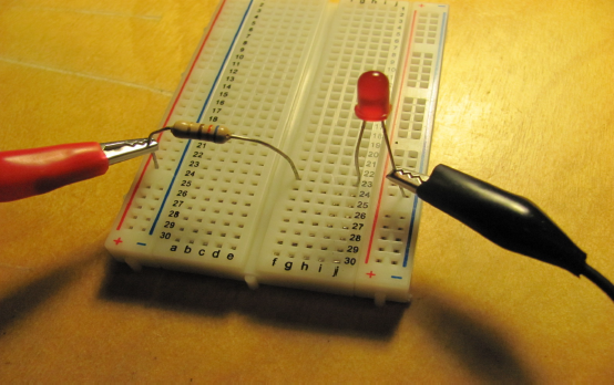
Notice the orientation of the red LED with the cathode terminal (flat spot) connected to the negative power lead.
9V Battery
A battery provides a source of energy for the circuit.
The battery outputs electrical pressure (voltage).
The battery outputs electrical current when connected to an electronic circuit.

Taking Some Measurements
- Turn on the multimeter and select the DC Voltage function (the V symbol with the straight line, not the wiggly line).
- Examine the battery. Identify the positive and negative terminals. Hint: the positive terminal as a + symbol beside it.
- Connect the multimeter probes to the 9V battery. The red lead to the positive terminal and the black lead to the negative terminal. What is the magnitude of the battery voltage. (Hint: it should be over 9V for a charged battery).
- Reverse the leads: black to positiv, red to negative. What happens to the reading? (Hint: it should reverse polarity).

- Let’s return to the LED circuit.
- Connect the 9V battery to the battery clip. The LED should illuminate.
- Measure the voltage across the LED by touching the multimeter leads to the LED leads. Touch the red lead to the anode of th LED and the black lead to the cathode. The voltage should be around 2V.
- Note that the voltage across the LED is much lower than the supply voltage (the battery).
- Measure the voltage across the resistor. The voltage should be around 7V.
- Note the relationship of the two components in the circuit to the supply voltage: the sum of the voltage across the resistor (7V) and the voltage across the LED (2V) are the same as the supply voltage (9V)

Two LED Circuit

The schematic above will allow us to light up two LEDs with the 9V battery.
- Both LEDs must be pointing in the same direction. Remember LEDs (diodes) only allow current flow in one direction.
- The current must flow from the positive terminal of the battery, through the resistor, then through the anode and cathode of each LED then back to the negative terminal of the battery.
- The cathode terminal of the the LED is adjacent to a flat on the plastic package. You can also look inside the LED. The terminal with the anvil is the cathode.

Here is the modified circuit with two LEDs. The anode of the green LED connects to the resistor. The cathode of the green LED connects to the anode of the red LED. The red wire connects to the positive terminal of the battery. The black wire connects to the negative terminal of the battery.
Flasher Circuit

The schematic above will allow us to flash the LEDs.
Note: In some kits, the flashing LED is yellow.
Hints
- Wire the resistor and flasher LED first. Make sure polarity is correct. The flat on the LED is the cathode.
- Connect the power and check that the LED flashes correctly.
- Add the red and green LEDs. Carefully check the polarity of the LEDs.
- Power up and watch those LEDs flash!
How Does it Work?
- When the flash is ON, the voltage across it is about 3.3 volts. This is also the voltage across the two series LEDs (red and green). This voltage is too low to allow the series LEDs to conduct current, so they are off.
- When the flasher turns OFF, the voltage starts to rise toward the supply voltage (9 volts). When it reaches the conduction voltage of the two series LEDs, they turn on. The voltage then stops at around 3.7 volts.
- Eventually, the flasher turns ON again and the cycle repeats.

We have installed the flasher LED (which is blue in some kits and yellow in others) in parallel with the red and green LEDs.
Make Some Noise

In this exercise, we will connect the speaker to the CircuitGear and make some noise!
Waveform Generator and Loudspeaker
- Plug the BNC-Clip lead into the output (generator) terminal of the CircuitGear hardware.
- Connect the alligator clips to the terminals of a loudspeaker.
- Start the CircuitGear software. Identify the Waveform Generator section of the controls.
Making Noise
- Move the Amplitude slider to maximum (100).
- Move the Frequency slider to approximately 1000Hz.
- Select the Sine waveform.
- You should now be hearing a cheerful noise from the speaker.
- Try moving the frequency slider up and down. Try and find the highest audible frequency and the lowest audible frequency.
- Try selecting different waveforms: square, triange, sawtooth, noise. (For the noise waveform especially, you’ll need to be close to the speaker to hear it.).
Hints
- Frequency is a bit easier to set if it’s limited to the audible range. The range of human hearing is often given as 20Hz to 20,000Hz, so we will set the frequency slider to run between those two values.
- Click on the button at the top of the frequency slider. An entry box will appear. Enter 20000.
- Click on the button at the bottom of the frequency slider. Enter 20.
- Now you can adjust the frequency more precisely. If you want an exact frequency, click on the frequency readout.
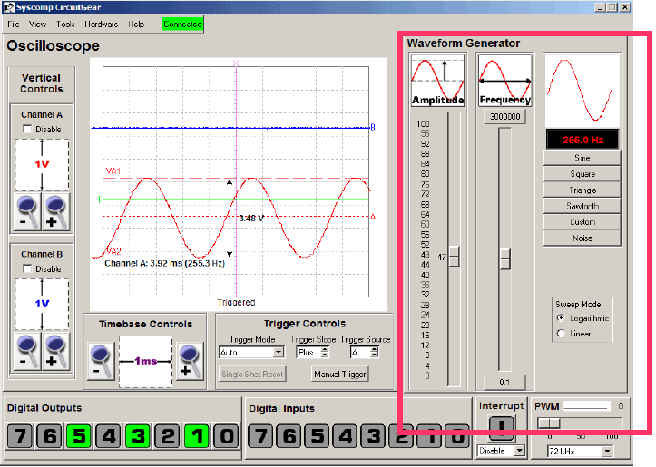
The waveform generator controls are shown in the red box. In newer versions of the software, it may be a separate window.
Connecting the Oscilloscope
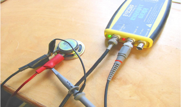
We can use the oscilloscope to view the speaker waveform signal.
- Connect a scope probe or alligator clip lead to channel A of the CircuitGear.
- Connect the alligator clips leads to the speaker terminals.
- Make sure to connect the ground clip of the oscilloscope probes (or the black clip of the alligator leads) to the speaker terminal with the black alligator clip from the waveform generator.
- Make sure to connect the scope probe or red alligator clip to the speaker terminal connected to the red alligator clip from the waveform generator.
Observing the Speaker Waveform
- Set the waveform generator amplitude to maximum (100).
- Set the generator frequency to 1000 Hz.
- Select sine wave.
- Set the Vertical Controls Channel A vertical sensitivity to 50mV. Each major vertical division on the screen now represents 0.05V.
- Set the Timebase Controls to 200uSec, so that each major horizontal division is 200/1000000 second (200 one-millionths of a second).
- You should have a sine wave display, as shown in the image. You will see some random noise because the signal is quite small compared to environmental electrical noise.
- This is a display of Voltage vs Time.

The oscilloscope controls are shown in the red boxes. Set the Channel A Vertical Sensitivity to 50mV/div (each vertical box is 50mV). Set the Timebase control to 200us/div (each horizontal box is 200us.

Oscilloscope Amplitude Cursors
- On the oscilloscope click on the menu item View–>Toggle Channel A Cursors (you can also right-click on the oscilloscope display to select the cursors from the pop-up menu).
- Drag the cursors to the top and bottom of the waveform.
- Drag the arrow readout to a convenient place on the display.
- This shows you the peak-to-peak voltage of the waveform.

Oscilloscope Time Cursors
- On the oscilloscope click on the menu item View–>Toggle Time Cursors (you can also right-click on the oscilloscope display to select the cursors from the pop-up menu).
- Drag the cursors to the start and finish of one cycle of the waveform.
- The readout shows the time for one cycle and its inverse which is the frequency in Hz.
Capturing a Transient Event with the Oscilloscope
The oscilloscope is an ideal device to capture a transient event, something that happens briefly and too quickly for human observation.
- Disconnect the waveform generator output cable leaving only the oscilloscope probe connected to Channel A.
- On the oscilloscope, set the Vertical Control Channel A to 5 volts per division.
- Until now, we have used Auto Triggering mode which gives a repetitive display. We want a single display that is captured until we are ready to clear it.
- Under Trigger Controls set Single Shot mode. Click on the Single Shot Reset button.
- Move the trigger cursor (the green horizontal cursor with the letter T at the left) to about +4V (two full divisions above zero).
- With the oscilloscope probe connect the black alligator clip to the negative terminal of the 9V battery.
- Touch the oscilloscope probe (or red alligator clip) to the positive terminal of the battery. This causes the voltage in Channel A to jump up from zero to 9 volts, triggering the oscilloscope.
- You should now have a record of that event, similar to the image.

A screenshot of a captured transient event. Notice how the voltage snaps up from zero to 9V when the probe touches the positive terminal of the battery.
The Capacitor
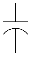
The schematic symbol for a capacitor.
- Capacitors store electric charge like battery.
- They can be polarized or non-polarized.
- Some capacitors have a voltage limit and may explode if the limit is exceeded.
Capacitor Circuit Function
- When the capacitor is connected to the 9 volt battery, it eventually charges up to 9 volts.
- Current flows from the battery when the capacitor is charging.
- The resistor limits the rate at which the capacitor is charged. A larger resistance causes a slower rate of charging.
- Larger capacitors charge more slowly for a given current into the capacitor.
- In this exercise, we will capture the capacitor charging with the oscilloscope.

Capacitor Charging Circuit

Setup for the capacitor charging circuit.

Closeup of the capacitor charging circuit.
- Set up the circuit shown in the schematic and wiring photos. Notice the polarity of the capacitor. The negative lead goes to the battery black lead.
- Do not connect the red alligator clip lead to the red lead of the battery just yet.
- Set up the oscilloscope:
- Vertical sensitivity to 2 volts per division on Channel A.
- Timebase set to 50 ms per division.
- Trigger cursor set to 4 volts above the zero line.
- Trigger controls: select single-shot, click on the single-shot reset button.
- Now touch the red alligator clip lead from the circuit to the red battery clip lead. This will cause the capacitor to charge to 9 volts at a rate determined by the values of the resistor and capacitor.
- This is known as an exponential charging curve because the rate slows down as it approaches (but never quite reaches) its final value, which is 9 volts in this case.
- The Time Constant, which is the time for the curve to reach about 70% of its final value, turns out to be RC, the product of the resistance and capacitance.

A screenshot of the voltage captured as the capacitor charges.
Measuring Sine Wave Amplitude and Phase
- Many electronic networks are designed to modify the amplitude and phase of a sine wave.
- In this exercise, we will show the effect of frequency on a so-called “RC Low Pass Filter”

RC Low Pass Filter Circuit
The Warbler: A Light-Controlled Oscillator

Warbler Schematic
Use this circuit to amaze and annoy your friends and family!
The Warbler
- The warbler circuit use an integrated circuit, the 555 timer, to drive a speaker.
- The frequency of the speaker signal is determined by how much light is hitting the photoresistor.
How it Works
- The 555 timer sets thresholds at 1/3 and 2/3 of the supply voltage. These thresholds are 3V and 6V.
- The capacitor C1 begins to charge through the photoresistor RP1 and resistor R1 toward the supply voltage 9 volts.
- When the voltage on the capacitor reaches the upper threshold (6V), the 555 timer trips an internal switch, causing a discharge path to appear at pin 7. The capacitor discharges through the photoresistor RP1 towards 0V.
- When the voltage on the capacitor reaches the lower threshold (3V), the discharge path shuts off. The capacitor again starts charging towards 9V.
- Net result: the capacitor voltage ramps upward and downward between 3V and 6V.
- Inside the 555, there is a device called a flip-flop which changes its state as the capacitor charges and discharges.
- The output of this flip-flop is a square waveform, which is synchronized to the capacitor waveform.
- The square wave drives the loudspeaker.
- Light changes the resistance of the photoresistor. More light causes lower resistance, which allows the capacitor to charge and discharge more quickly. Consequently, the audible frequency increases with more light.

Waveforms from the Warbler Schematic
- Trace A shows the capacitor voltage. Notice how it ramps between +3V and +6V.
- Trace B shows the square wave voltage that drives the speaker. It has an amplitude of 1V and changes with the ramp waveform.
Building the Warbler: The Parts
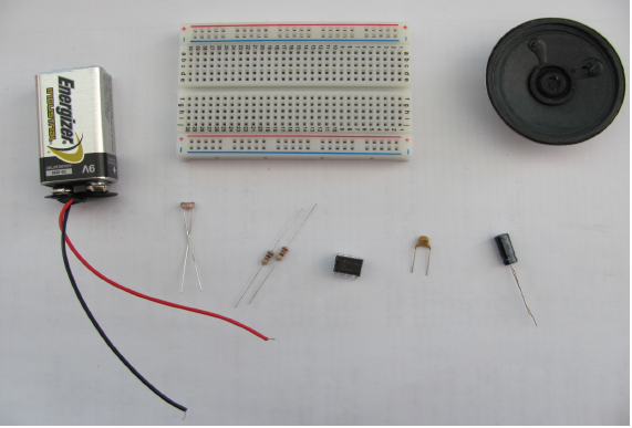
All the parts we need to assemble the Warbler.
- 9V Battery
- Battery clip with red/black wires
- Breadboard
- Speaker
- Photoresisitor
- 1k resistor (brown-black-red)
- 120R resistor (brown-red-brown)
- 555 timer IC
- 220nF ceramic capacitor (small brown one)
- 47uF electrolytic capacitor (large cylindrical one)

Placing the 555 Timer IC
Plug the 555 timer into the protoboard. The "top" of the IC is denoted by the notch in the case.

555 Timer Pinout
This diagram shows the pin layout of the 555 timer IC.

Positive Connection to Pin 8
Connect a wire between one of the power rails and pin 8.

Ground Connection to Pin 1
Connect a wire between pin1 and one of the other power rails.

Add Ceramic Capacitor
Connect the 220nF ceramic capacitor between pin 2 and the ground rail.

Connect Pins 2 and 6
Connect a wire between pins 2 and 6 of the 555 timer.

Connect Photoresistor
Connect the photoresistor between pins 6 and 7 of the 555 timer.

Add Resistors
Connect the 1k resistor (brown-black-red) between pins 7 and 8 of the 555 timer. Connect the 120R resistor (brown-red-brown) between pin 3 and an empty row on the protoboard.

Add Electrolytic Capacitor
Connect the 47uF electrolytic capacitor between the other end of the 120R resistor and an empty row on the protoboard. Note: the positive lead of the capacitor must connect to the resistor. The negative lead is marked with a stipe and/or "-" negative symbol.

Add Ground Wire
Plug a length of wire into the ground rail and connect an alligator clip lead (the white lead in the photo). Connect another alligator clip lead to the negative pin of the capacitor. Clip the yellow and white alligator lead to the two terminals on the speaker.
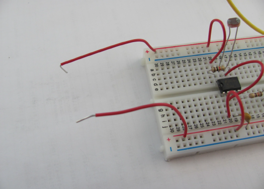
Add Power Wires
Add two wires to the power and ground power rails on the protoboard. This will make it easy to connect the battery.

Final Connections
VERY IMPORTANT: Make sure the red battery lead connects to the positive power connection. The black lead goes to the common (ground) connection. An incorrect connection will destroy the 555 timer.
- At this point, your circuit should be making a cheerful noise.
- Experiment with blocking light from the photoresistor and observe the effect on the sound.
- To shut off the circuit, disconnect the positive (red) clip lead from the battery.
- If the circuit is not working, make a copy of the schematic. Then cross off each and every connection on the schematic as you check that connection of the protoboard wiring.
- Pro Tip: To make your Warbler extra annoying, connect the flasher LED circuit and point the LED at the photoresistor!
Parts List
The following components are included in the electronics parts kit.
- Breadboard/Protoboard
- Alligator Clip Leads
- 9V Battery
- 9V Battery Connector
- 680 ohm resistor
- Red LED (non-flashing)
- Photoresistor
- Green LED (non-flashing)
- Blue LED (flashing)
- Speaker
- Capacitor, 47uF, 16V
- Resistor, 1kohm
- Capacitor, 220nF
- Integrated Circuit, 555 Timer
- Resistor, 120 ohm


